Physical LED Controls
ECE Discovery Project
Overview
This project explores the design and construction of a custom USB control board with mechanical switches and sliding variable resistors, build to control various LED devices based on real-time input. The system uses both embedded and desktop software to send input data over USB, interpreted by desktop software which uses OpenRGB to control lighting effects and configurations. The device was built from scratch, including hardware design, prototyping, soldering, and case assembly, demonstrating a hands-on, iterative approach to embedded systems and interaction design.
Goals
The main objective for this project was to create a versatile and configurable control surface for LED lighting setups. Some specific goals I set for myself were:
- Designing a physical interface with multiple input types (sliders and switches)
- Enabling user reconfiguration of control behavior (e.g. a single slider could control brightness, hue, or effect speed)
- Implementing USB communication for broad OS compatibility
- Building a finished device housed in a custom casing
- Successfully integrating with OpenRGB, an open-source API for lighting control
I chose this project in order to improve my ECE skills, specifically targeting USB data transfer, and physical fabrication.
Successes and Failures
What went well:
- The embedded software worked reliably and was adaptable to the control scheme
- The transition from breadboard to soldered hardware went smoothly
- The USB-based communication with OpenRGB was successfully implemented and debugged
- The physical layout of the board offered good usability and response
What didn't go as planned:
- Design and parts ordering took longer than expected, delaying hardware prototyping
- Not all planned computer-side features (like a GUI) were implemented by showcase time
- Building and soldering the final hardware took more iteration than anticipated, which compressed portfolio writing and presentation time
Skills Gained
This project was a deep dive into real-world application of embedded electrical and computer engineering principles. Key skills developed include:
- Soldering and hardware finalization: Moving beyond prototyping to polished, finished hardware
- Circuit design and planning: Creating a clear component layout with minimal signal interference
- USB protocol understanding: Learning how to interpret and transmit structured data over USB
- Embedded-to-desktop communication: Coordinating signal input from the board with software logic on a PC
- Iterative design and project pacing: Realizing the importance of buffering time for troubleshooting and adjustments
Process
I started the process with research on how to create custom USB devices. This specific topic had me going in circles for quite a while, however, I ended up settling on the Arduino Micro. This was an ideal solution, since the board already has built-in USB capabilities, and I am already familiar with board in the arduino family.
Next up, was finding all the additional components I would need for this build. This included the slide potentiometers, as well as knobs for them, and blank keycaps for my mechanical switches. The rest of the parts were needed specifically for the final build. These included some PCB prototype boards to solder onto, and some extra jumper wires. Other than that, I already had all of the pieces I would need.
Once I had picked out all the pieces, I got to designing the circuitry that would allow the board to actually read from the switches and sliders. This circuitry was fairly simple, consisting of mainly just connecting power, ground, and the analog and digital input pins of the right places. The original design that I planned to prototype only used two buttons and two sliders.
After designing the fairly simple circuitry, and waiting for all my parts to arrive, I was ready to build a prototype on a breadboard. I pretty quickly put together a prototype of my 2-button-2-slider design on a couple breadboards, then wrote some test code for that simply plotted the button and slider values in the using the debugger. I could see that both the buttons and sliders were working as intended, meaning that the hardware prototype was successful!
Once the hardware prototype was successful, I modified the embedded software in a few ways:
- To be easily able to change the number of buttons and switches for the final board
- And to send signals via USB only when a value changes, or when the device is polled
After making these changes, I ran the embedded software again on the prototype hardware, and I eventually got it to work as intended. The final embedded code can be downloaded here.
The desktop side software ended up being a pretty simple task, all it had to do was receive USB input, decode it, and then send that data back to the OpenRGB sdk. I ended up implementing this code in python, and it can also be downloaded here.
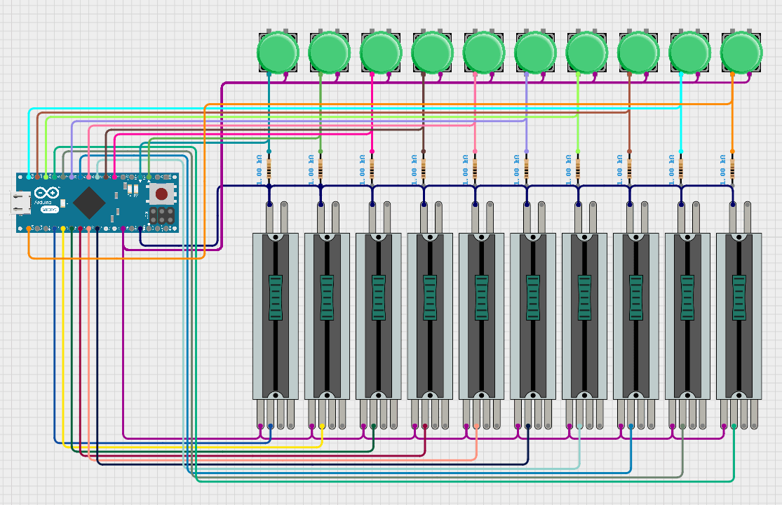
Just one more thing before moving onto the final hardware. Before I started wiring on the finalized hardware, I updated my wiring diagram for the 10-slider-10-button final design. This ended up being super helpful, since all 20 inputs ended up using a lot of the Arduino Micro's available pins, and finding space for all of the inputs while wiring would have been a lot more stressful. That final pin plan is shown below:
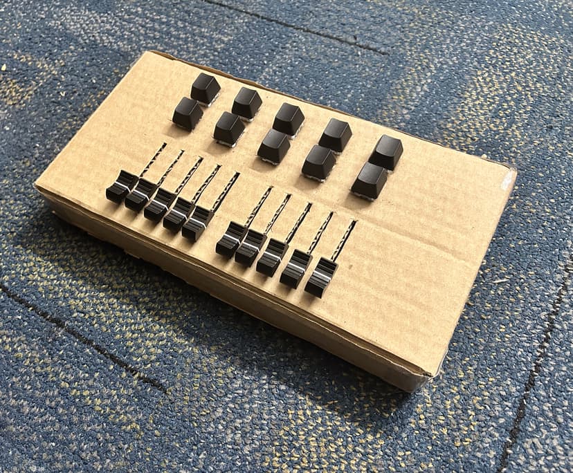
Finally, I was able to start constructing the final design. When I initially set out on this project, I had wanted to improve my physical fabrication skills, and use the tools provided by the makerspace to 3D print a housing for the components in the final design. However, I did not end up having enough time to accomplish this. What I ended up doing instead, was I put together a casing using a cardboard box! Through some meticulous box cutting and hot gluing, I arrived at a pretty clean final product.
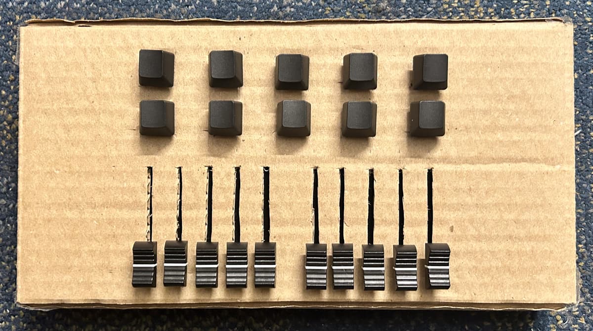
Now for the final step, placing and soldering all the electronics. This took me quite a while. But luckily, I had already set myself up for success by planing the exact wiring that I would need execute. After many hours spent improving my soldering skills, I finally finished wiring the full circuit.
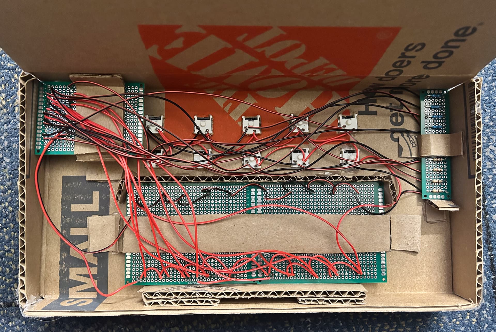
Once that was done, I retested the embedded software on the final build, and thankfully everything was working. After making just a few tweaks to the desktop-side software, I was able to get the basic controls working! Here is a short demo showcasing the final product: