The Machine
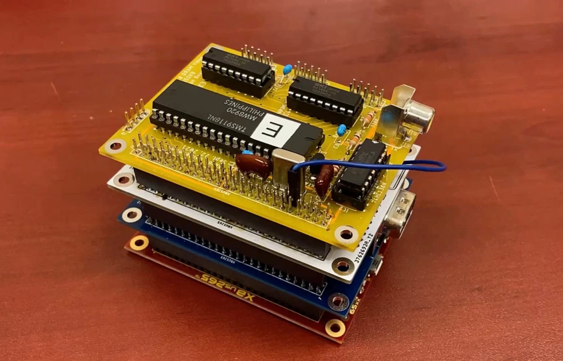
RetCom87 is a team inside Georgia Tech’s Vertically Integrated Projects program building a retrofuturistic, 80s-inspired computer. It’s a stack of boards on top of a WDC W65C265SXB, whose 65C816 CPU (the 16-bit successor to the 6502, best known from the Super Nintendo) drives a sound board, a TMS9118 video board, and keyboard and controller input.
My part was the software side. With no operating system underneath, everything I wrote is 65816 assembly, loaded onto the board over serial. I kept a lab notebook throughout the year, and this page is drawn from it.
Learning 65816 Assembly
I started by working through the ChibiAkumas 6502 and 65816 tutorials, then wrote three practice programs, each one leaning on more of the processor. I uploaded each to the physical board with WDC’s easySXB tool, ran it, and dumped memory to check the result by hand.
Modulo (6502 emulation mode)
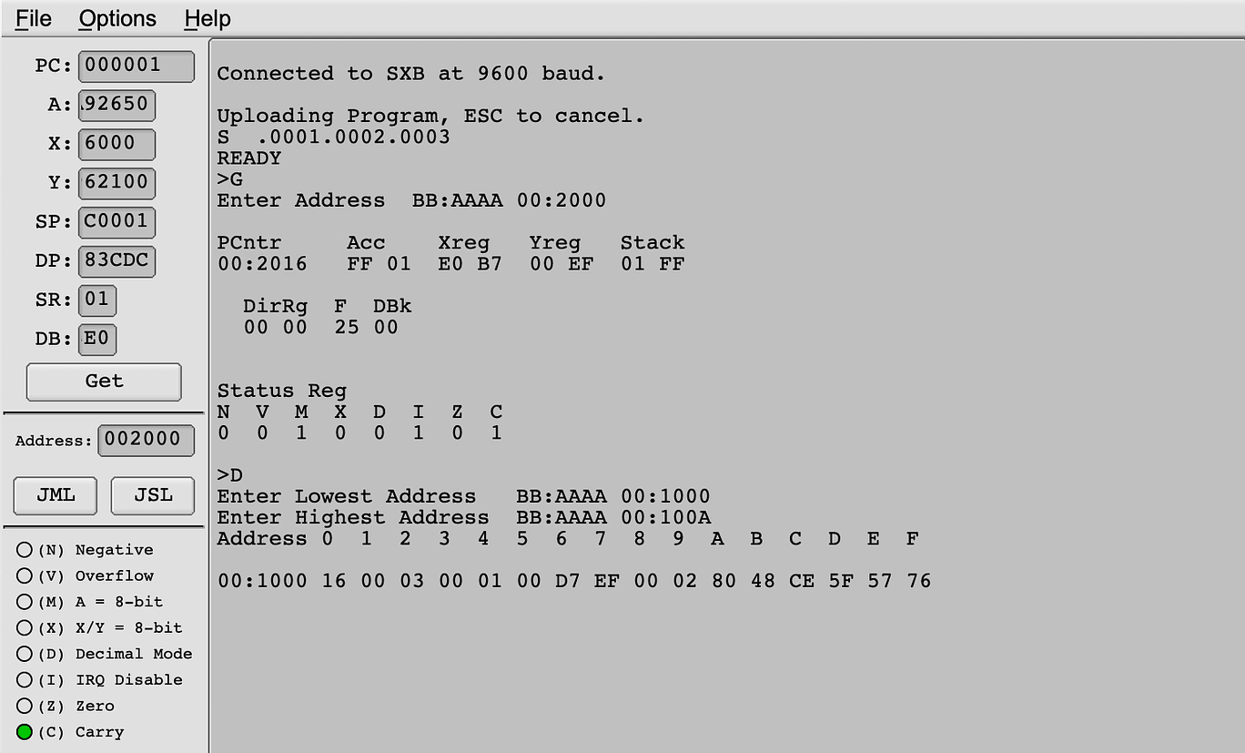
A repeated-subtraction modulo, written entirely in 6502 emulation mode to get comfortable with branching and the basic instruction set. The memory dump shows A = 0x16 (22), B = 0x03, and RESULT = 0x01, so 22 % 3 = 1.
Shift-and-add multiply (native mode)
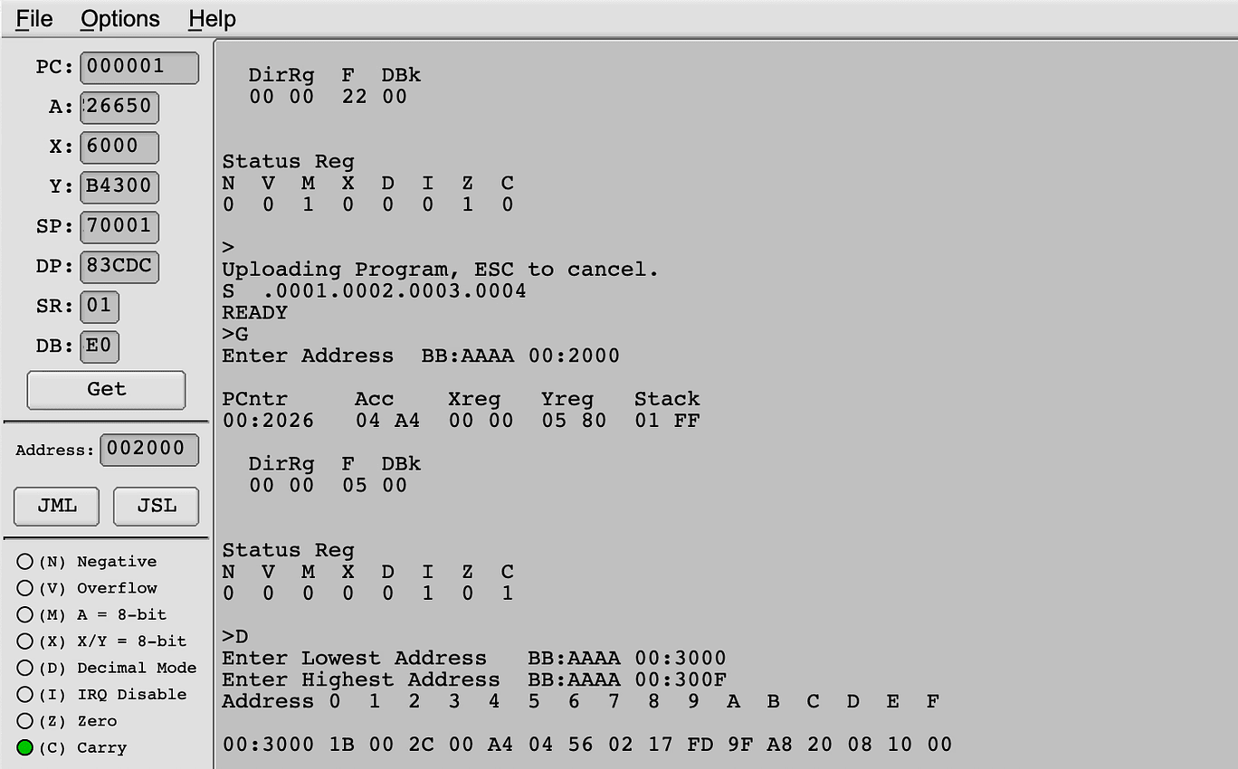
The next step was native mode. Setting the accumulator and index registers to 16 bits allows larger operands, and the algorithm multiplies with shifts and adds instead of a loop of additions.
.65816
    org 0x3000
A:      dw 27
B:      dw 44
RESULT: dw 0

    org 0x2000
start:
    sei
    clc
    xce             ; switch to native mode
    rep #0x30       ; 16-bit accumulator and index registers
    ldx A
    ldy B
loop:
    txa
    and #1          ; low bit of A set?
    beq skip
    tya
    clc
    adc RESULT      ; RESULT += B
    sta RESULT
skip:
    tya
    asl             ; B <<= 1
    tay
    txa
    lsr             ; A >>= 1
    tax
    bne loop
done:
    lda RESULT
brkRecursive quicksort
The last exercise was a quicksort over a 20-byte array, written with recursive subroutines that take their arguments in the X and Y registers and return in the accumulator. It runs with an 8-bit accumulator (to read bytes) and 16-bit index registers, and it relies on the stack and zero page far more than the first two programs. Getting it to work on easySXB was hard, and the board’s breakpoints weren’t helping. That’s what led to the debugger below, where I tracked down every bug before moving the program back onto the hardware.
Building a 65816 Debugger
To see exactly what my code was doing, I wanted to run it somewhere I could fully observe and control. After testing several emulators, I built on Francesco Rigoni’s Lib65816, a C++ implementation of the 65816 CPU, and extended it into a command line debugger that can:
- Load
.hexprogram files - Dump memory to, and load memory from, a binary file
- Add and remove breakpoints
- Step into, over, and out of code after a breakpoint is hit
- Print the current CPU status
- Set the program counter directly, or run from any address
Testing it on my own programs turned up a bug in the original library: one of the arithmetic opcode handlers used the accumulator’s 8/16-bit mode when it should have used the index registers’ mode. Once that was fixed, the debugger became the tool four of us on the sub-team used to learn 65816 and track down bugs. The source is on GitHub. One issue is still open there: after a brk instruction, execution won’t resume even after the PC is reset.
Debugger Demo
This video is a walkthrough of the debugger and its command line features, running 65816 code entirely in software, without the board.
Driving the TMS9118 Video Chip
Text mode
The video board is built around a TMS9118, the same family of video chip used in the ColecoVision and MSX. I began by modifying the team’s existing demo to put my own strings on screen: initialize the chip’s eight registers for text mode, copy a font into the pattern table in VRAM, then write characters into the name table.
Timing matters. The CPU can write faster than the chip can accept data, and an interrupt landing mid-write puts the two out of sync, so interrupts stay off while the code talks to the chip.
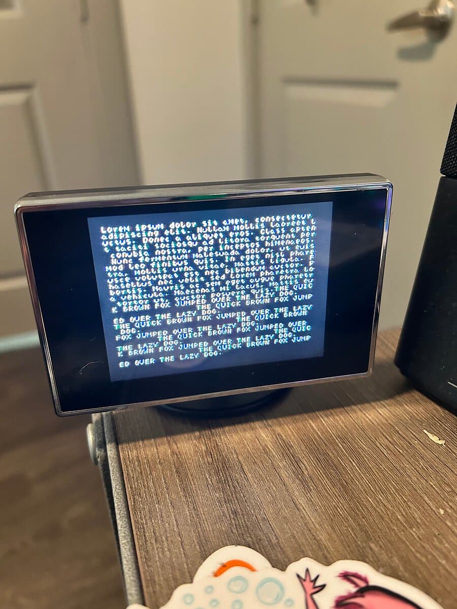
;ports for TMS9118
VDATA = $DFD0         ;VRAM data sequential reads/writes
VREG  = $DFD1         ;Register read/writes and initial VRAM address

start:
  sei                 ;never let an interrupt split a VDP write
  sep #$30

  ldx #$00            ;index into data table
  ldy #$80            ;code for register 0, will increment
init_loop:
  lda TEXTMODE_INIT, X
  sta VREG            ;write data
  nop                 ;cannot write too fast or the VDP can't keep up
  sty VREG            ;write register identifier
  inx
  iny
  cpy #$88            ;all 8 registers written?
  bne init_loop

TEXTMODE_INIT:
  .byte $00 ;R0 = Text mode, no external video
  .byte $d0 ;R1 = 16K, Enable Display, Disable Interrupts
  .byte $02 ;R2 = Name table in VRAM at $0800
  .byte $80 ;R3 = Color table not used
  .byte $00 ;R4
  .byte $20 ;R5 = Pattern table in VRAM at $0000
  .byte $00 ;R6
.byte $F1 ;R7 = White text on black backgroundSprite mode
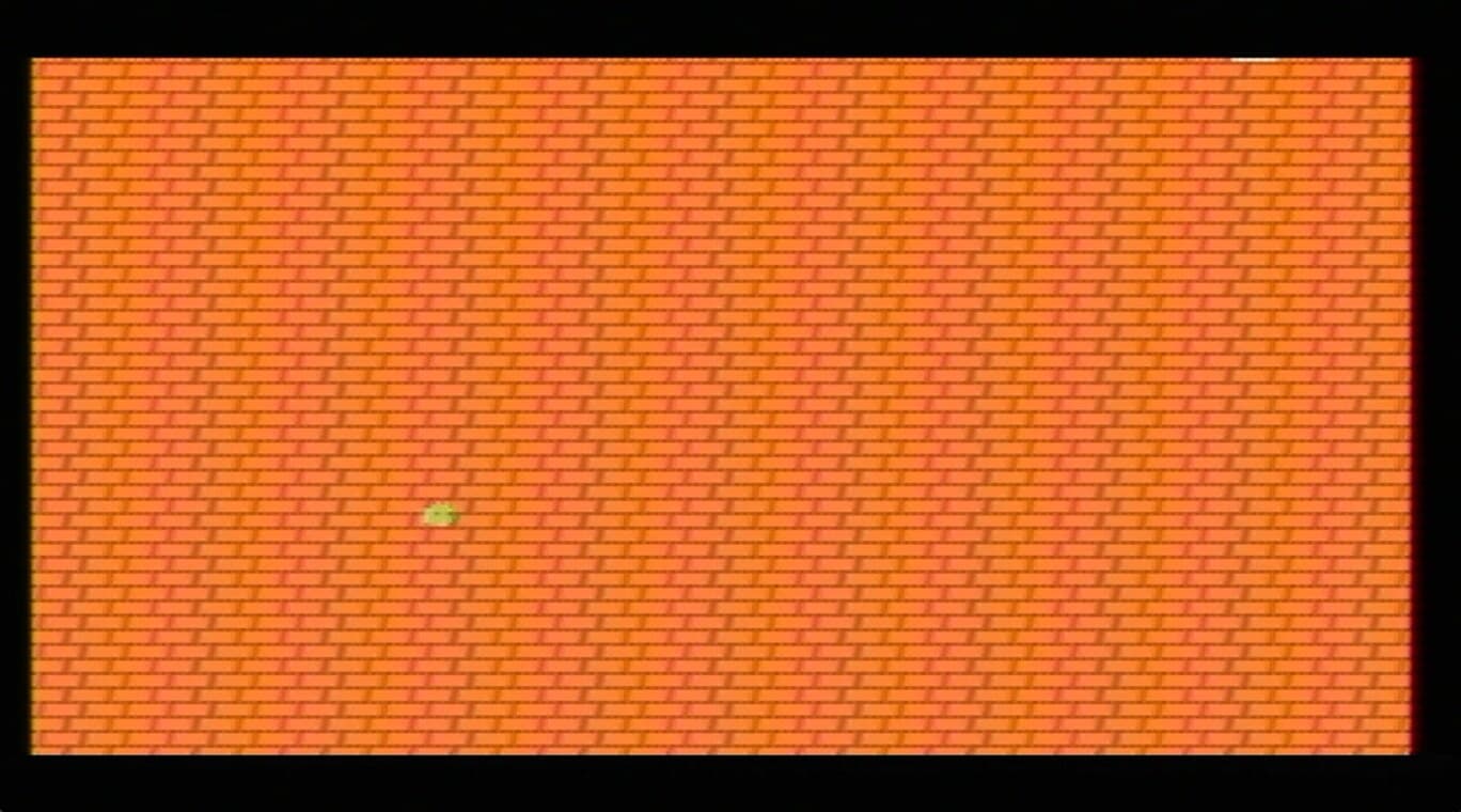
Sprites took a while to click. My answer was a reusable template: the program carries all of its VRAM data (patterns, colors, and sprite attributes) and copies each block to the right place. The demo uses both background patterns and sprites in Graphics I mode, with a small sprite moving down the screen over a tiled brick background. For now, motion comes from a busy-wait between each pixel of movement. The next step is driving it from a hardware timer instead.